
Introduction
Tuner Pro is a powerful free (but not open) map editing program that runs under Windows. Out of the box there are no definition files available for the TD5 ECU so we need to create a XDF file from scratch.
The creation process requires a good understanding of the ECU file format you are creating the definition for. At a minimum this means understanding where the tables are located and how they are structured.
Step 1: Finding the Tables
As a starting point you will need a hex editor. I primarily use OSX and have been using Hex Fiend [ http://ridiculousfish.com/hexfiend/ ] as my primary editor. I’ve also used 0xED [ http://www.suavetech.com/0xed/ ] and that is possibly even better for the task at hand. I haven’t really used Windows or Linux Hex Editors so can’t recommend anything specific - I’m sure there are decent tools out there.
Once you have got your hex editor installed the first thing to do is open up your .map file. It’s actually easier to work with a straight .bin of the fuel map as it avoids a lot of the messing around with offsets…
The loaded file should look something like this:
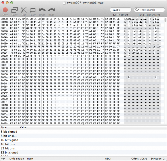
The index of maps is located at an offset of 0x1CEFE from the start of the map file. Using the hex editors “go to position” , “go to offset”, or “move selection to” , enter the offset 0x1CEFE and hit return to get to first entry in the index list. As an aside “0x” indicates the number is hexadecimal, and the hex editor might require you enter this prefix. Hex Fiend does, 0xED doesn’t.

The map addresses are 2 bytes or 16 bits long, and the first map address should be 0x0934 in the EU3/15P maps at least. This address is an offset from the beginning of the fuel map. Because the Nanocom map format bundles both the variant and fuel map together it is necessary add the offset from the start of the .map file to the beginning of the fuel map. This should be 0x19010 for all NNN ECU’s.
Putting this together we now know that the ECU reference to the first map is: 0x19010 + 0x934 = 0x19944.
At offset 0x19944 you see the following:
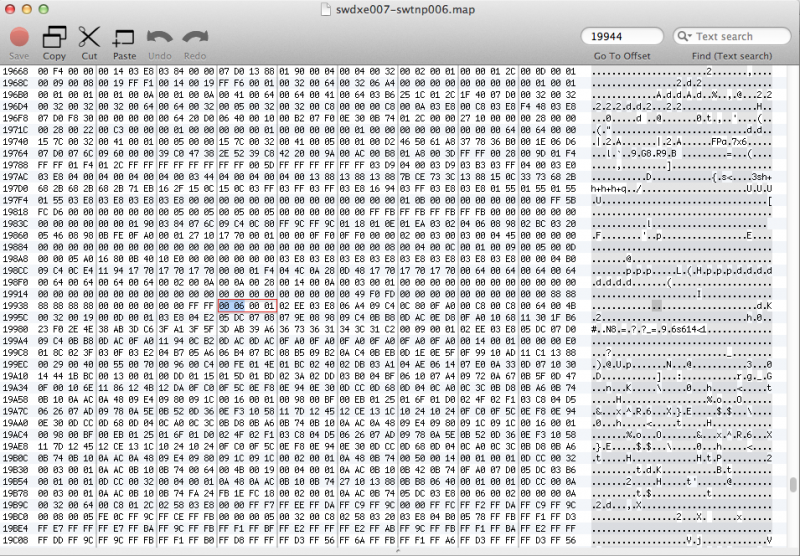
This is the start of the definition of “Map 000”.
Step 2: Decoding the Map Definition
Once the index of map addresses has been located, and the method for locating the start point of each map definition is understood, we need to look at how the information in each definition is structured in order to extract useful information.
The map definition has the following format:
| column count (2 bytes) | row count (2 bytes) | column headers (2 bytes * column count) | row headers (none if row count = 1, else row headers (2 bytes * row count) | map data ( 2 bytes * column count * row count) |
So looking at the definition for map000/0x934 beginning at 0x19944 we can see that this 2D map has:
- 6 columns
- 1 row
- 6 column headers
- 0 row headers
- 6 items of data
When creating a definition for Tuner Pro the key pieces of information are:
- Number of Rows
- Number of Columns
- Start address of Map Data
- Start address of Row Headers
- Start address of Column Headers
The number of rows and columns are easy to obtain, but the other information requires a bit of simple math.
We know the start address of the map definition - 0x19944 offset from the start of the .map file in the case of Map 000.
The column and row counts each take 2 bytes, or a total of 4 bytes. So adding 4 bytes to the address of the map gives the start address of the column headers: 0x19948.
The column headers take up 2 bytes * number of columns. In this case 0x2 * 0x6 = 0xC which is added to the address of the column headers to find the next segment of the definition. As Map 000 has one row, and therefore a 2D table, there is no row header and the next segment beginning at 0x19954 is the map data.
The procedure is basically the same for every table. With 3D tables, you need to account for the size of the row headers but this is the only real difference.
Step 3: Creating a Tuner Pro Definition
Armed with the addresses for the table we can begin to create a map definition in Tuner Pro.
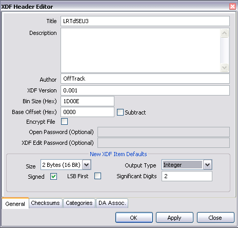
From the XDF menu in Tuner Pro select “New XDF”, then “View/Edit XDF Header Info”.
Starting from the top, fill out Title, Author, XDF version. The Nanocom .map file is 0x1D00E bytes long, so enter this into the “Bin Size (Hex)” field. Set the New XDF Item Defaults to “Size: 2 bytes (16 bits)”, “Signed - ticked”, “Output: Integer” and “Significant Digits: 2” , then “Apply” and “Close”. At this point it’s a good idea to save the XDF definition.
Step 4: Defining a Map
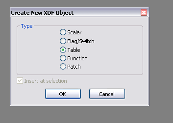
From the XDF menu select “Create new XDF Parameter. At the dialog that appears select “Table” and continue.
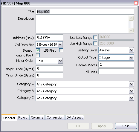
The next task is to fill in the Tuner Pro map definition. Name the tale something meaningful. It’s possibly worth following the Td5 Map Editor conventions here with Map000 -> Map 115.
Address needs to be filled with the start address of the map data. In the case of Map 000 this is 0x19954. As we know from earlier discussion of the ECU map structure the cell data size is 2 bytes. This is all that is really essential for this page.
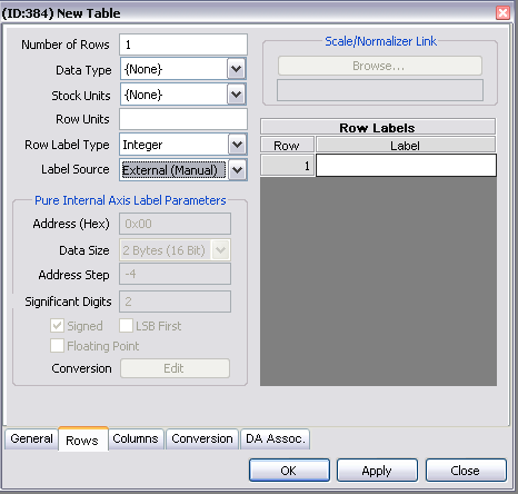
Switch to the Row tab. For a 2D table with one row, all that is required is to enter 1 in the “Number of Rows”.
Switch to the Columns tab.
Here we need to enter a bit more information. “Number of columns” is set to 6, then Label Source is set to “Internal, Pure”. This enables an extra section of configuration options which allows setting the location of header data.
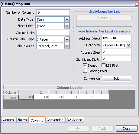
In the section “Pure Internal Axis Label Parameters” section enter the start address of the column headers, in this case 0x19948. Data size is set to 2 bytes (16 Bits), Address Step to 2 and Significant Digits to 2. Once you are done click Apply then Close.
At this point you should save the XDF file.
Step 5: Load a map file
From the file menu select “Open Bin…”, set the file type to “All Files (.)” then open up an EU3 TD5 map file.
Once you have both an XDF and “Bin” open you should be able to click on the Map000 in the Parameter tree display.
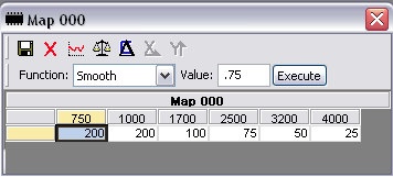
This will give you a floating window of the table with headers and data.
Clicking on the graph icon will give you a graphical display of the same information.
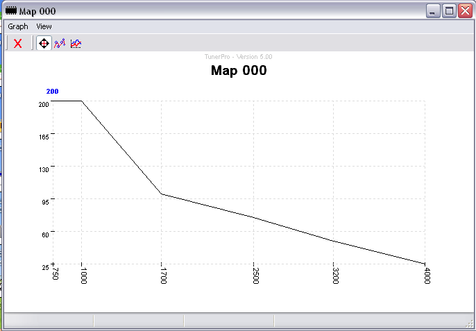
Step 6: Repeat until done…
The same process is repeated for each table you need to edit. There a lots of tweaks and refinements available but they aren’t necessary for basic editing.
End Note: Finding map addresses
Obviously the procedure for locating map addresses detailed above is painfully slow, and is given primarily so the process of finding the tables and how this portion of the fuel map is structured is clear. There is nothing worse than blindly following instructions with no understanding of the “why”.
A more practical solution is to set up a calculator in Excel. By using the HEX2DEC, DEC2HEX and IF functions it is reasonably straight forward to make a spreadsheet to do the grunt work. In fact I'm wondering why I didn't make one earlier.
The attached archive is an XLSX spreadsheet that calculates the three hex address required to configure the tables for Tuner Pro. The required inputs are Table address, number of columns, number of rows. You can select a base address of 0x19010 (if you are using the full map files) or 0x0 (if you are editing the fuel map only). It's also possible to select the row and column counts as dec(imal) or hex(idecimal).
The easiest way to get the base address and column and row sizes is to open the .map file you want to work with in Td5 Map Editor and read of the information from the table index list.