ECU Reverse Engineering

MSB trivia - three way throttle support

Sunday, October 9, 2022 - 16:00

I came across an oddity in the MSB000080 and MSB101360 code while trying to understand why the map structure in those ECU's is slightly different to other MSB and NNN EU2 maps.

Most have an unused Ambient Air Temp sensor input which will display values from a connected AAT via diagnostics but otherwise don't use the values. The MSB000080 and MSB101360 are slightly different and looking at the code I realised that the AAT input was being used for as a third-track throttle input.

The throttle code used in MSB000080 and MSB101360 is the same as in the NNN ECU's. These two models have support for three way throttle, and appear to have diagnostic support for setting throttle ways. Note this is different to diagnostic tools supporting making changes - I don't have either unit here so difficult to test.

The way-3 values are reported by diagnostics as an AAT reading in the temperature sensors request, and the throttle diagnostics report only ways 1 and 2, throttle amount and supply voltage.

It's probably something to file under "So what do we do with that?"

Td5 Injector Idle Codes

Saturday, March 6, 2021 - 11:30

Given my recent posts about bugs in the Nanocom's handling of injector idle codes I thought I'd pull together some background information.

Codes

The documentation on injector codes indicates that the injector idle letter codes map to numeric values. These numeric values are 0-based indexes for idle adjust tables which are located in the fuel map. Each idle code maps to an adjustment ranging from -0.075ms to +0.075ms in EU2 maps, and -0.047ms to +0.047ms in EU3 maps.

ECU Hardware

At the most basic level the MSB and NNN have different limitations on the value that can be saved.

The MSB masks the values sent by the diagnostic tool by performing the equivalent of modulo 4 of the value sent by the diagnostic tool. The effect is that if you send an idle code of 5 to an MSB it saves 1 to eeprom.

The NNN masks values with the equivalent of modulo 16, meaning it can save values In the range of 0-15 to eeprom.

10P maps and NNN

Regardless of whether running on MSB or NNN hardware 10P (EU2) maps mask the injector code to modulo 4.

This snippet in python demonstrates the effect. % is the modulo operator.

mask = 4
for i in range(9):
    print(f"{i} modulo {mask} = {i % mask}")
 
"""
Output:
0 modulo 4 = 0
1 modulo 4 = 1
2 modulo 4 = 2
3 modulo 4 = 3
4 modulo 4 = 0
5 modulo 4 = 1
6 modulo 4 = 2
7 modulo 4 = 3
8 modulo 4 = 0
"""

So while the diagnostic code will allow programming of 15P idle codes to an NNN running a 10P map, the map will use the 0-3 10P coding.

The effect is that the 10P coding is repeated for the higher 15P codes...
15P: 1, 2, 3, 4, 5, 6, 7, 8
10P: 1, 2, 3, 0, 1, 2, 3, 0

Code for the map, not the ECU

It should be clear from the above that injector codes are interpreted based on the map being run rather than "earlier" or "later" ECU's. The ideal here is to use the correct map for the injector type and engine, and set the idle codes accordingly.

Idle adjust tables

I mentioned earlier that the idle codes are index values. So let's look at what that means in practice.

10P idle

I briefly had the hidden 10P idle map defined in the XDF's but removed as it was causing significant confusion.

For reference this is what the idle adjust table looks like:

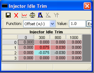
The x-axis is rpm, and y-axis is the numerical idle code for black/blue top injectors. What we can see from this is that idle codes 0 and 3 are both 0ms adjustment across the board. So the equivalence of A = 0,3 makes perfect sense. Index 1 is a positive adjustment, ranging from 0.075ms at 300rpm, 0.030ms at 800rpm and 0ms at 1000rpm. Index 2 is a negative adjustment which is the mirror of Index 1: - 0.075ms at 300rpm, -0.030ms at 800rpm and 0ms at 1000rpm.

Interpolating the values indicates that the adjustment at 760rpm is +/- 0.033 ms depending on code 1 or 2.

You'll notice that In 10P maps idle adjustment has no effect above 1000rpm.

15P idle

The 15P maps have the idle adjust map defined as a standard table.

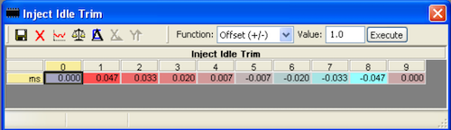
This is obviously very different to the 10P map. The rpm axis is gone and there are now 10 columns with indexes in the range of 0-9. Looking at the time adjustments in each column it becomes apparent that 0 and 9 are the equivalent of rows 0 and 3 in the 10P map.

With this in mind it should be fairly obvious why the equivalence of M = 0, 8 looked highly questionable. It's simply not a valid statement to say 0ms is the same as -0.047ms.

The idle codes with values roughly follow the arrangement of the 10P table. Columns 1-4 contain positive adjustments, 5-8 contain negative adjustments which mirror the first 4 values.

10P codes 1 and 2 roughly align with 15P codes 2 and 7 respectively.
This should give a clue how it would be possible to code injectors when running a 15P map on 10P hardware:
- "B" is equivalent to "F"
- "C" is equivalent to "L"

I'll update further when I have some time, but this should give some basis for understanding the issues behind the injector coding bugs I've described.

The "Bad Land Rover Engineering" Myth and .map Programming

Tuesday, June 16, 2020 - 13:00

I'm sure you've heard that the reason NNN ECU's get bricked when uploads fail is due to some variation on the "Bad Land Rover Engineering" theme. The spiel on many LR forums is familiar: "NNN: Worst flash programming ever. Blame the incompetent Land Rover engineers."

It turns out that is a myth.

While doing the disassembly I'd found code than indicated that the ECU had routines to checksum uploaded variant and fuel map code and checked that specific bytes were set in both the variant and fuel maps. I didn't really dig any further with that, as Nanocom .map files always had the specific bytes configured.

Then a couple of weeks ago a long time supporter sent me a link to Andrew Revill's K-Series reverse engineering project. Andrew has done some fantastic work with the K-Series NNN, including an NNN flash programmer application that works with a dumb VAG interface.

Reading the description of his programmer triggered an "Ah ha" moment..

It's taken bit of messing around over the past couple of days but I've now managed to confirm that the Nanocom supports "brick proof" programming. The problem is that none of the maps produced for the Nanocom I've seen - from stock tunes produced by the MapWizard to .tun protected commercial remaps - are set up to use the functionality.

Rather than having "worst programming eva" the NNN has an extremely robust mechanism which only makes the ECU bootable after the fuel map has been completely programmed and the data has been verified. But only if the uploaded map ticks all the boxes.

The video shows the "ignition" being turned off after roughly 3KB of the fuel map has been programmed.
Under normal circumstances this would have guaranteed a bricked ECU.

With the "brick proof" configuration of the .map, the ECU boots back into programming mode and the Nanocom connects without any problems.

As an aside I was having major issue with 1.34 firmware on the Nanocom. Yesterday it came up with a black screen and "cannot find NC image" error message. After installing the 1.35 update, then installing again and wiping the configuration after discovering the unlock codes were completely scrambled it is working far better.

A tool that will update .map files to the "brick proof" format is in the works...

MSB map switching

Wednesday, April 17, 2019 - 07:00

I was having a look at the MSB diagnostics a couple of days ago and came across the request for switching between maps.
Some MSB ECU's - most often the Auto versions - come with tunes for multiple markets and the switching function provides a method for selecting the correct tune.

NOSELECT "Tune"

The NOSELECT tune is default on a new spare ECU. The tune provides just enough functionality to start an engine.
The duration maps are 2 x 2 tables that have rows for 0 and 750 rpm, so should allow the engine to idle.

The remaining tunes are full market specific fuel maps.
In this case the ECU is an MSB1011191 and has tunes for European and Japanese Auto D2s.

European Auto Tune

Japanese Auto Tune

With some minor modifications to the .bin this ECU should support at least one additional fuel map.
The NOSELECT "tune" seems to be referenced in several places during startup so possibly needs to be retained as is.

Even so this opens up the possibility of software switching between two or three maps without resorting to additional hardware to perform address line switching hacks.

MEMS ain't MEMS

Monday, March 18, 2019 - 18:45

I've been working on a disassembly of a K-Series engine map that runs on an NNN petrol MEMS ECU for last day or so.

While there is a basic level of commonality with the Td5 this is very much restricted to low level drivers and some utility functions, like map lookup and interpolation, basic kline drivers, CANBUS drivers, etc, etc.

It's this type of functionality that accounts for the similar appearance of the ECU fuel maps. The lookup for sensor scaling is pretty much identical, even though the actual processing has significant differences, for example.

Once you move beyond this "housekeeping" code, you are firmly into the realm of engine specifics.

So yes, MEMS are similar up to a point - but this also hides a lot of difference in the actual engine code.

In other words "MEMS ain't MEMS"

AAP/AAT sensor swapping

Friday, April 7, 2017 - 12:15

This is a fairly niche modification.

EU2 and EU3 engines are fitted with significantly different airbox sensors.

The EU2 uses a three wire Ambient Air Pressure sensor, while the EU3 uses a four wire Ambient Air Pressure/Ambient Air Temp sensor.

The curve of the AAP portions of the two sensors are different and require different parameters to give the correct reading.

Without adjusting the parameters there is a misread of around 10kPa. You'll get an over-read ( -700 m altitude) with EU2 AAP + EU3 tune, and under read (+700m altitude) with EU3 AAP + EU2 tune.

The problem is not so bad with EU2 AAP + EU3 tune as the engine assumes higher air density in some correction maps and will INCREASE injected fuel and give a 0.1 bar increase in the boost limit. The boost level is MAP - AAP so reducing AAP by 0.1 results in boost levels 0.1 higher than the would be with correct setup. I suspect this is why you often hear the comment that an EU3 tune drives better that the correct EU2 tune.

If you've addressed the issue by installing a 4-wire sensor - replace airbox lid, sensor and run an extra wire back to the ECU - the problem occurs when you want to run an EU2 map on the motor. The under-read means the ECU uses corrections which reduce the fuelling plus the boost limit is reduced by 0.1 bar. It guarantees bad performance.

The fix is in

The way to fix this problem is to use the correct parameters for the AAP you have installed. Search for the values for the base map and replace with values for the sensor you are using.

EU3 - 4 wire sensor
multiplier: 13171 ( 0x3373 )
offset: 267 ( 0x010B )

EU2 - 3 wire sensor
multiplier: 10410 ( 0x28AA )
offset: 1227 ( 0x04CB )

It's not too hard to find these values with a hex editor as I think they are fairly unique. As a rough guide they are somewhere around an offset of 0x6A0 from the start of the fuel map. In a Nanocom .map the fuel map always begins at 0x19010.

The donor-ware XDF's now have a patch that swaps the values. It's a bit rough as it shows a stock EU3 tune as being patched, so installing the EU2 parameters requires "reversing" the patch.

Td5 NNN ECU "Base" Code

Sunday, March 5, 2017 - 14:15

NOTE: This post has been updated to reflect that the driver chips NOT related to injector control. Rather these chips are used for things like PWM outputs to the instrument panel.

One of the very early posts one this site shows a diagram of the firmware layout used on the Td5 NNN ECU's.

The portion of memory located between addresses 0x0000 - 0xFFFF was cryptically called "ECU Base Code", with the note that this is not touched during Nanocom .map uploads.

The "Base" code is possibly better described as management or boot loader code. In normal usage the main function it performs is basic setup of the ECU hardware, verifying that certain check points are present in the Variant and Fuel maps, then running the variant map code if everything correct.

The secondary function of the management code is to provide support for factory programming of the ECU. Without a variant or fuel map installed the ECU will boot into a special diagnostic mode that provides access to the functions need to upload .map files, program injector codes, synchronise with the BCU immobiliser, and set the throttle pedal type. I assume this mode would have been used on the production line to program new ECU after installation into a vehicle.

The management code is identical across all the NNN ECU's with two minor differences.

The first difference is the code identifier. Like engine maps each variant management has a unique identifier. The second difference is the ECU hardware code, which reflects the well know NNN numbering. So the thbtp001 ecu code has the indentifer NNN000120, whereas the thbtp005 has the identifier NNN500250.

The complete list is:

NNN000120: thbtp001
NNN000130: thbtp002
NNN500020: thbtp003
NNN500030: thbtp004
NNN500250: thbtp005

If you are simply uploading .map files using a diagnostic tool you don't need to worry about this as the management code is not touched even if you brick the ECU.

Where you can run into problems is if you upload a complete .bin file from a different ECU type.

One of the differences between the NNN000xxx and NNN500xxx ECU's is that the power driver chips used to control the injectors pwm output and some switches were changed from Intersil HIP0060 to Infineon TLE6220GP parts. While both types of chips use Serial Peripheral Interface bus to communicate with the MCU the format of the messages and the representation of faults differs.

The ECU code uses the identifier from the management code to determine which driver chip is present.

So if you fit a .bin from a NNN000120 to a NNN500020 or NNN500250 for example the Variant code will read the NNN000120 identifier and use the code for the HIP0060 driver chip, rather than the TLE6220GP.

What makes this problematic is that one chip arranges it's fault codes:

A_OverTemp, B_OverTemp, C_OverTemp, D_OverTemp,  A_OpenLoad, B_OpenLoad, C_OpenLoad, D_OpenLoad

with a value of 1 signalling a fault.

The other uses:

A_bit1, A_bit2, B_bit1, B_bit2, C_bit1, C_bit2, D_bit1, B_bit2

If both bit1 and bit2 are set to value of 1 the channel is operating normally, and if both are set to zero there is a "short to ground" fault present.

This means if you send the diagnostic bits from a HIP0600 showing no faults (all zeros) to an ECU configured for a TLE6220GP the best you can hope for is "short to ground" faults on all channels.

The injector fault checking is called in the main loop of the ECU code and it's potentially updated every 10 milliseconds or so. I haven't been able to confirm how this impacts general running, but I've been speaking to someone who has had ongoing issues with poor starting who appears to be running NNN000120 management code on an NNN500250 so it seems fairly likely this is related.

Anyway, it's something to be aware of...

Saleae Logic

Saturday, December 21, 2013 - 18:00

I've been having a bit of trouble getting my head around what is happenning of the SPI bus of the Td5 ECU, so I've given in and ordered a Saleae Logic 8 channel logic analyser as a solstice present to myself.

First up on the hit list when the parcel arrives is working out the read and write protocols to the EEPROM that is used to store things like injector codes, logged fault codes and immobliser codes. Ultimately it should be possible to use this information to write a script to dump the EEPROM contents, modify the injector codes, disable the immobilser, etc.

The other task that I have lined up is sorting out the canbus communications with the Autobox. I have identified the routines which process canbus communications, but need to see what data is transmitted over the bus in normal operation. There appears to be a significant amount of configuration information related to the canbus and I'm intrested to see if any of this is sent to the Autobox ECU. 

Update:

I've had a quick play with the Logic 8 and it seem to do what it says on the box. I hooked up to the signal lines to the eeprom and triggered off the first rising edge of the clock and captured a big block of reads from the EEPROM. The the first lot of read requests tallied with what I'd worked through on paper so looks good. I'll have to wade through and verify the responses are being decoded correctly.


Capture of eeprom read command


Reverse engineering the Td5 ECU

I've spent a bit of time over the past few months trying to get my head around the firmware for the TD5 ECU. It's been a long tedious process but things are slowly falling into place.

I'd been puzzling over how the fuel map table were looked up and finally found the routine used to look up the tables. The key point is there is an index of tables addresses near the end of the fuel map. The variant map looks up the address of the required table using the index and then calls the table lookup with the address of the table and the values for the x and y variables. The subroutine returns a value based on this information which is then processed as required.

By referring to "known" tables listed in the Td5MapEditor application, I've been able to make some inroads into the way the tables are used, but it is still far from straight forward. The descriptors of the variables in Td5MapEditor don't really capture the complexity of the process.

As an example the fuel maps are described as a function of the RPM and throttle position. I've traced the "throttle position" input back through three levels of subroutines and still haven't hit a direct reference to the throttle position. The subroutine preceding the fuel map lookup modifies the "throttle position" variable based on two maps, one of which is applied if the revs are below 1000rpm, the other if the revs are above 4200rpm. If the revs are between 1000 and 4200 the values from both maps are extrapolated from the 1000rpm and 4200rpm values.

ECU Clock Frequency

Update: After doing further work on ECU I've discovered that the none of the speculation originally reported in this post is accurate and should be ignored. After locating the code that handles clock setup for the OBD-II communications I've been able to determine the crystal is actually 4.0768Mhz and the system clock runs at 16.3072Mhz.

Old content begins here:

I'd come across a comment on a European forum that the ECU uses a 16.77Mhz crystal, so had been keeping that in the back of my mind while working with the code. I decided to have another look at this as it would be very handy to know for sure.

The crystal on the NNN500030 ECU I've been working with is soldered to the board at both ends, and the only visible marking is 23A18. I'd pondered the possibility that this is a hex representation of the frequency but it would have to a very unusual, although not entirely implausible result.

Checking back on the SIM documentation the CPU will accept a clock up to 20Mhz from an external source, but this requires that the clock signal be supplied on a single pin (EXTAL) and the second pin (XTAL) be left floating. This does not reflect the Td5 CPU layout, which appears to have a crystal attached as a reference for the internal Phase-Lock Loop. The allowable frequency range for the crystal in this case is 4.194 - 5.234Mhz.

Assuming the crystal is the 4.194Mhz used as a default value in the manual, then fsys is configured to 16.776Mhz.

It looks like I'll need to actually measure the crystal to see what frequency is being used, but at least it should be within the range that my multimeter can handle.

Pages

randomness