
This is a bit of background on how the physical waste gate modulator unit operates.
It has only been in the last few weeks that it finally dawned on me that I'd been uncritically accepting the "Active to Limit" theory as correct. While it doesn't seem that important on the surface, it's difficult to make sense of code when the behaviour seems to be at odds with how you believe the hardwares should be operating.
Let's start by looking the Active to Limit Boost theory of operation:
- power off, the valve is in an open position and boost flows from turbo outlet pipe to the Wastegate Actuator;
- power on and no PWM signal from the ECU, the valve is in a closed position and boost is prevented from reaching the Wastegate Actuator;
- power on and PWM signal from the ECU, the valve opens and allows boost to reach the Wastegate Actuator, opening the waste gate.
Active to Limit Boost is the most commonly expressed explanation of how the WGM operates, even if it's not explicitly stated.
This example is from Urban Panzer's excellent www.discovery2.co.uk website...
"trying to the rev the engine over 2500 RPM the waste gate modulator info that Nanocom shows under "read fuelling" went to zero occasionally, so it basically was not controlling turbo charger boost / waste at certain times and was very "hit and miss" at best. That all seems to make sense and description in RAVE would appear to confirm that view. And the Nanocom logs seem to suggest this is what happens in practice.
You can clearly see the WGM active = controlling boost, WGM inactive = boost uncontrolled aspects of the Active to Limit Boost theory.
You'll see this theory of operation informing most forum posts relating to over boosting and WGM diagnosis. It's difficult not to fall into this way of thinking due to it's prevalence - that's my excuse anyway.
So lets look at this in detail...
Hardware first
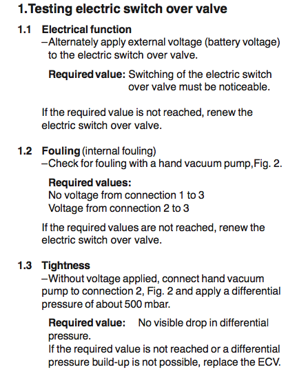
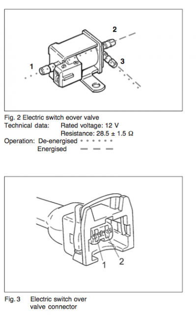
After a bit of digging I found a couple Pierburg service information sheets for electric switch over valves. These were for parts identical in appearance to the D2's waste gate modulator, but with different part numbers. The test methodology given in the service information required a hand vacuum pump, so I decided put the site donations fund to use and purchased a Mityvac kit. Thanks again to those who have contributed!
The test procedure is fairly straight forward, but the main question I had was whether the valve on the D2 behaved in the same way as described.
Testing the modulator on my D2 suggests that the flow through the modulator does match that outlined in the test procedures.
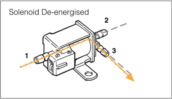
- power off, boost flows from turbo outlet pipe into port 1 for the modulator and out of port 3 to the waste gate actuator;
- power on, engine running, and no pwm, boost flows in from turbo outlet pipe into port 1 for the modulator and out of port 3 to the waste gate actuator;
In the course of doing these tests I discovered that while the WGM seemed to be OK, it wasn't passing the Tightness test 1.3.
It was possible to pull down to 0.5 bar vacuum but this dropped to 0 within roughly 10-15 seconds.
Similarly, applying pressure to port 1 with port 3 capped resulted in a loss of pressure over 10-15 seconds.
To confirm normal operation I ordered a Pierburg OEM modulator and bench tested.
Out of the box the modulator would hold 0.5bar vacuum on port 2 for 20 minutes with no visible loss of vacuum.
Testing with port 3 capped and 2.0 bar applied to port 1, there was no visible loss of pressure after 20 minutes.
The pin to pin resistance of the new WGM was 29.3ohm, which is within the 28.4ohm +/-1.5ohm specification.
Powered Benchtests
Rather than leave the testing hanging I decided to perform tests 1.1 and 1.2 from the Pierburg service information. This was done with a bench power supply and confirmed the new WGM behaved as described.
For test 1.1 Electrical Function there was distinct click as the solenoid activated, as you'd expect
For test 1.2 Internal Fouling the air flow matched the required values:
- no power: air flowed from port 1 -> port 3.
- power: air flowed from port 3 -> port 2.
The thing to note here is that port three is the common outlet. The solenoid is switching between port 1 and port 2.
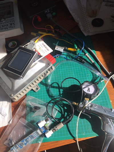
Next step was to connect the WGM to my tester ECU. Power to the + pin on the WGM was taken from the "master relay" on the interface board. The - pin was connected to A21 on the ECU.
I also hooked up the Bitscope Micro with the scope probe connected to the - pin and the earth clip hooked up to the power supply earth. Add in the Mityvac and Nanocom and it all starts getting a bit messy!
The main difference between unpowered (ignition off) and powered (ignition on) without a PWM signal is the voltage level.
Unpowered and no PWM gives 0V on both +ve and -ve pins.
Powered and no PWM gives supply voltage on both +ve and -ve pins.
Because there is no voltage differential between +ve and -ve no current flows and no "work" is done.
In the case of power applied to +ve pin and PWM operation, the +ve pin is at supply voltage and -ve pin at earth reference when the PWM completes the earth path. Because there is a voltage differential of around 13.5V and the solenoid coil has resistance around 29ohms the WGM will draw 0.46 amps and dissipated about 6.28 Watts when it is activated.
I can attest that leaving the WGM hooked up to a 12V supply for 5 minutes results in the WGM becoming hot to the touch. oops!
The Bitscope capture below shows the Nanocom Wastegate Modulator Test in action.
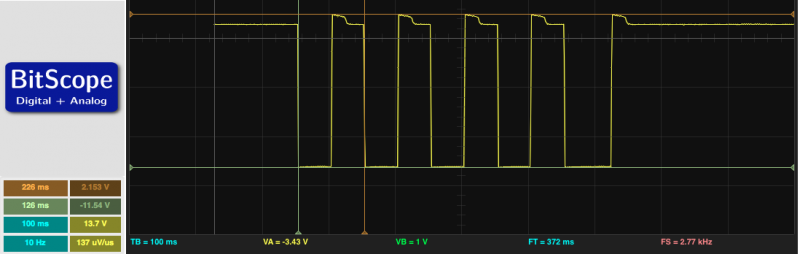
You can see the effect of the PWM completing the earth path resulting in the voltage at the - pin of the WGM dropping by just under 12V.
The pulse width is 100ms or 10Hz, and the duty cycle is roughly 50%, which corresponds with frequency and duty cycle requested by the Nanocom test routine.
I couldn't work out how to capture on video but with the port 3 capped and port 1 pressurised to 2 bar, there was a distinct "puff" as pressure was released through port 2 each time the WGM activated.
As can been seen from the video the WGM is directing pressure to the capped port 3 when it's not receiving a PWM signal.
When PWM is active the pressure in the capped waste gate actuator outlet is released via port 2.
The small drop in pressure seen on the gauge with each activation is due to the small internal volume of the cap I've used.
Revised Theory of Operation
At this point it should be apparent the theory of operation outlined at the start of the post was a bit back-to-front.
Updating the theory to reflect real world behaviour we get:
- power/ignition off, air pressure flows from port 1 (turbo outlet) -> port 3 (waste gate actuator) - wastegate receives full boost
- power/ignition on, and no PWM signal, air pressure flows from port 1 (turbo outlet) -> port 3 (wastegate actuator) - wastegate receives full boost.
In these cases the WGM is de-energised.
- power/ignition on and PWM signal, air pressure flows from port 3 (waste gate actuator) -> port 2 (turbo intake pipe) - wastegate isolated from full boost.
In this case the WGM is energised.
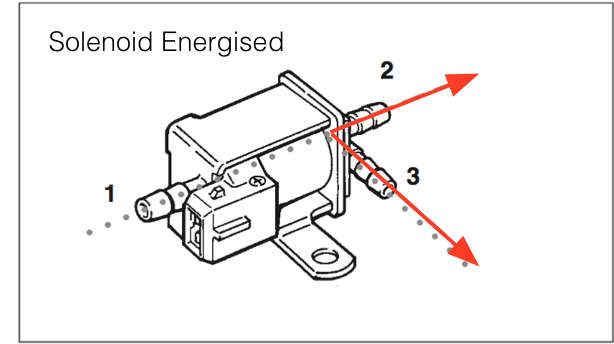
This means when the WGM is recieving a PWM signal it is operating to reduce pressure at the Wastegate Actuator. Rather than "Activate to Limit Boost" the system is "Activate to Increase Boost".
But RAVE says...
So what does RAVE actually say to support the "activate to limit boost" theory?
The following sentence is often pointed to as evidence:
When full boost is reached a control signal is sent to the wastegate modulator, and a vacuum is applied to the wastegate valve.
Interestingly this sentence incorrectly states that vacuum rather than boost operates the waste gate valve. This is often excused as a typo but there is clearly an error in the statement.
Nothing else in RAVE indicates a specific method of operating, just that the system controls boost pressure to prevent overboost.
What about the Nanocom logs....
The Nanocom samples engine data once every 1.2 seconds in the current EVO guise - Nanocom 1 was a bit quicker at 1 second.
The WGM control code samples boost pressure and engine load once every 10ms and updates the PWM amount at that speed.
This means the WGM PWM has potentially been updated 120 times for each data point the Nanocom logs show. Transitions between PWM on and off to control limit boost occur quite quickly. 500ms is not uncommon, and the actual switch off occurs faster than the 70ms sample time of the logs.
In conclusion...
Looking back at the opening quote it's pretty obvious what is occurring.
... the waste gate modulator info that Nanocom shows under "read fuelling" went to zero occasionally, so it basically was not controlling turbo charger boost / waste at certain times and was very "hit and miss" at best.
The waste gate modulator PWM drops to 0% because the ECU is trying to direct full boost pressure to the waste gate actuator. And from the diagnostic information you can surmise the failure mode is either loss of spring tension in the valve or internal fouling of the modulator.
The next post in the Wastegate Modulator series will look at the WGM control maps.